- UML Tutorial
- UML 2.0 Overview
- UML Useful Resources
- Utilities
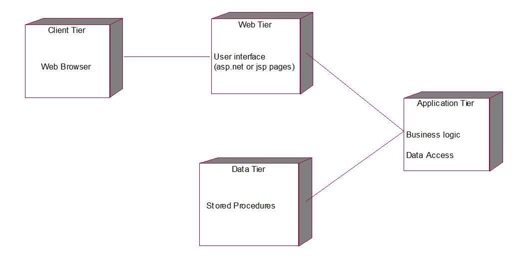
This is a Component diagram of Student Management System which shows components, provided and required interfaces, ports, and relationships between the Logins, Courses, Fees, Exams and Student. This type of diagrams is used in Component-Based Development (CBD) to describe systems with Service-Oriented Architecture (SOA). The Student Information system is a server-based system that uses an Object-Oriented approach to manage student registration at the department level. It consists of good data integrations features, good GUI to enhance user experience and flexible reporting features to deliver value to users. In our design, we present the approach that extends the relational database system of managing student registration to an Object Database Management System.
- Selected Reading
Object diagrams are derived from class diagrams so object diagrams are dependent upon class diagrams.
Object diagrams represent an instance of a class diagram. The basic concepts are similar for class diagrams and object diagrams. Object diagrams also represent the static view of a system but this static view is a snapshot of the system at a particular moment.
Object diagrams are used to render a set of objects and their relationships as an instance.
Purpose of Object Diagrams
The purpose of a diagram should be understood clearly to implement it practically. The purposes of object diagrams are similar to class diagrams.
The difference is that a class diagram represents an abstract model consisting of classes and their relationships. However, an object diagram represents an instance at a particular moment, which is concrete in nature.
It means the object diagram is closer to the actual system behavior. The purpose is to capture the static view of a system at a particular moment.
The purpose of the object diagram can be summarized as −
Forward and reverse engineering.
Object relationships of a system
Static view of an interaction.
Understand object behaviour and their relationship from practical perspective
How to Draw an Object Diagram?

We have already discussed that an object diagram is an instance of a class diagram. It implies that an object diagram consists of instances of things used in a class diagram.
So both diagrams are made of same basic elements but in different form. In class diagram elements are in abstract form to represent the blue print and in object diagram the elements are in concrete form to represent the real world object.
To capture a particular system, numbers of class diagrams are limited. However, if we consider object diagrams then we can have unlimited number of instances, which are unique in nature. Only those instances are considered, which have an impact on thesystem.
From the above discussion, it is clear that a single object diagram cannot capture all thenecessary instances or rather cannot specify all the objects of a system. Hence, the solution is −

First, analyze the system and decide which instances have important data and association.
Second, consider only those instances, which will cover the functionality.
Third, make some optimization as the number of instances are unlimited.
Before drawing an object diagram, the following things should be remembered and understood clearly −
Object diagrams consist of objects.
The link in object diagram is used to connect objects.
Objects and links are the two elements used to construct an object diagram.
After this, the following things are to be decided before starting the construction of the diagram −
The object diagram should have a meaningful name to indicate its purpose.
The most important elements are to be identified.
The association among objects should be clarified.
Values of different elements need to be captured to include in the object diagram.
Add proper notes at points where more clarity is required.
The following diagram is an example of an object diagram. It represents the Order management system which we have discussed in the chapter Class Diagram. The following diagram is an instance of the system at a particular time of purchase. It has the followingobjects.

Customer
Order
SpecialOrder
NormalOrder
Now the customer object (C) is associated with three order objects (O1, O2, and O3). These order objects are associated with special order and normal order objects (S1, S2, and N1). The customer has the following three orders with different numbers (12, 32 and 40) for the particular time considered.

The customer can increase the number of orders in future and in that scenario the object diagram will reflect that. If order, special order, and normal order objects are observed then you will find that they have some values.
For orders, the values are 12, 32, and 40 which implies that the objects have these values for a particular moment (here the particular time when the purchase is made is considered as the moment) when the instance is captured
The same is true for special order and normal order objects which have number of orders as 20, 30, and 60. If a different time of purchase is considered, then these values will change accordingly.
The following object diagram has been drawn considering all the points mentioned above
Where to Use Object Diagrams?
Object diagrams can be imagined as the snapshot of a running system at a particular moment. Let us consider an example of a running train
Now, if you take a snap of the running train then you will find a static picture of it having the following −
A particular state which is running.
A particular number of passengers. which will change if the snap is taken in a different time
Here, we can imagine the snap of the running train is an object having the above values. And this is true for any real-life simple or complex system.
In a nutshell, it can be said that object diagrams are used for −
Making the prototype of a system.
Reverse engineering.
Modeling complex data structures.
Understanding the system from practical perspective.
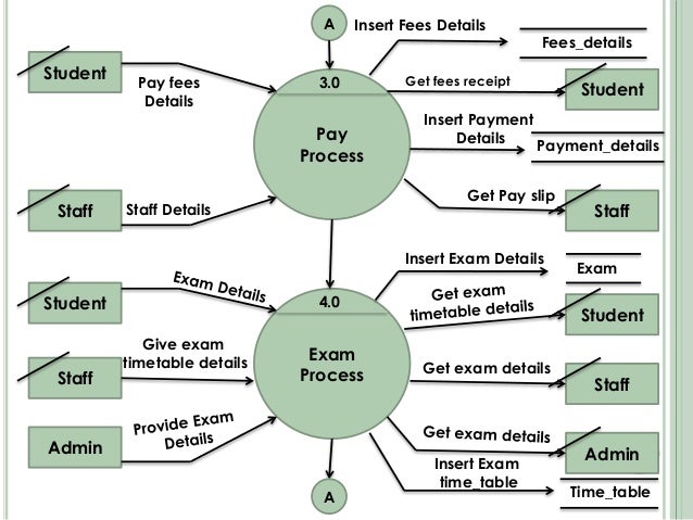
DFD for Student Management System Project
A data flow diagram is a graphical view of how data is processed in a system in terms of input and output.
The Data flow diagram (DFD) contains some symbol for drawing the data flow diagram.
Data flow diagram(DFD) for Online shopping website
A data flow diagram is a graphical view of how data is processed in a system in terms of input and output.
The Data flow diagram (DFD) contains some symbol for drawing the data flow diagram.
Data flow diagram symbols
| Symbol | Description |
| Data Flow – Data flow are pipelines through the packets of information flow. | |
| Process : A Process or task performed by the system. | |
| Entity : Entity are object of the system. A source or destination data of a system. | |
| Data Store : A place where data to be stored. |
0 Level DFD – Student Management System
The 0 level dfd known as context level data flow diagram. The context level data flow diagram (dfd) is describe the whole system. The (o) level dfd describe the all user modules who run the system. Below context level data flow diagram of Student management system project shows the one Admin user can operate the system. Admin do all activities after login to system.

We have already discussed that an object diagram is an instance of a class diagram. It implies that an object diagram consists of instances of things used in a class diagram.
So both diagrams are made of same basic elements but in different form. In class diagram elements are in abstract form to represent the blue print and in object diagram the elements are in concrete form to represent the real world object.
To capture a particular system, numbers of class diagrams are limited. However, if we consider object diagrams then we can have unlimited number of instances, which are unique in nature. Only those instances are considered, which have an impact on thesystem.
From the above discussion, it is clear that a single object diagram cannot capture all thenecessary instances or rather cannot specify all the objects of a system. Hence, the solution is −
First, analyze the system and decide which instances have important data and association.
Second, consider only those instances, which will cover the functionality.
Third, make some optimization as the number of instances are unlimited.
Before drawing an object diagram, the following things should be remembered and understood clearly −
Object diagrams consist of objects.
The link in object diagram is used to connect objects.
Objects and links are the two elements used to construct an object diagram.
After this, the following things are to be decided before starting the construction of the diagram −
The object diagram should have a meaningful name to indicate its purpose.
The most important elements are to be identified.
The association among objects should be clarified.
Values of different elements need to be captured to include in the object diagram.
Add proper notes at points where more clarity is required.
The following diagram is an example of an object diagram. It represents the Order management system which we have discussed in the chapter Class Diagram. The following diagram is an instance of the system at a particular time of purchase. It has the followingobjects.
Customer
Order
SpecialOrder
NormalOrder
Now the customer object (C) is associated with three order objects (O1, O2, and O3). These order objects are associated with special order and normal order objects (S1, S2, and N1). The customer has the following three orders with different numbers (12, 32 and 40) for the particular time considered.
The customer can increase the number of orders in future and in that scenario the object diagram will reflect that. If order, special order, and normal order objects are observed then you will find that they have some values.
For orders, the values are 12, 32, and 40 which implies that the objects have these values for a particular moment (here the particular time when the purchase is made is considered as the moment) when the instance is captured
The same is true for special order and normal order objects which have number of orders as 20, 30, and 60. If a different time of purchase is considered, then these values will change accordingly.
The following object diagram has been drawn considering all the points mentioned above
Where to Use Object Diagrams?
Object diagrams can be imagined as the snapshot of a running system at a particular moment. Let us consider an example of a running train
Now, if you take a snap of the running train then you will find a static picture of it having the following −
A particular state which is running.
A particular number of passengers. which will change if the snap is taken in a different time
Here, we can imagine the snap of the running train is an object having the above values. And this is true for any real-life simple or complex system.
In a nutshell, it can be said that object diagrams are used for −
Making the prototype of a system.
Reverse engineering.
Modeling complex data structures.
Understanding the system from practical perspective.
DFD for Student Management System Project
A data flow diagram is a graphical view of how data is processed in a system in terms of input and output.
The Data flow diagram (DFD) contains some symbol for drawing the data flow diagram.
Data flow diagram(DFD) for Online shopping website
A data flow diagram is a graphical view of how data is processed in a system in terms of input and output.
The Data flow diagram (DFD) contains some symbol for drawing the data flow diagram.
Data flow diagram symbols
| Symbol | Description |
| Data Flow – Data flow are pipelines through the packets of information flow. | |
| Process : A Process or task performed by the system. | |
| Entity : Entity are object of the system. A source or destination data of a system. | |
| Data Store : A place where data to be stored. |
0 Level DFD – Student Management System
The 0 level dfd known as context level data flow diagram. The context level data flow diagram (dfd) is describe the whole system. The (o) level dfd describe the all user modules who run the system. Below context level data flow diagram of Student management system project shows the one Admin user can operate the system. Admin do all activities after login to system.
Object Diagram For Student Management System
1st level DFD – Student Management System
The Admin side DFD describe the functionality of Admin. Admin is a responsible person who run the project. After login to system admin can first Add Course Detail and Teacher Detail and then add student detail by course wise. and admin can manage student reports and fees payment detail.

